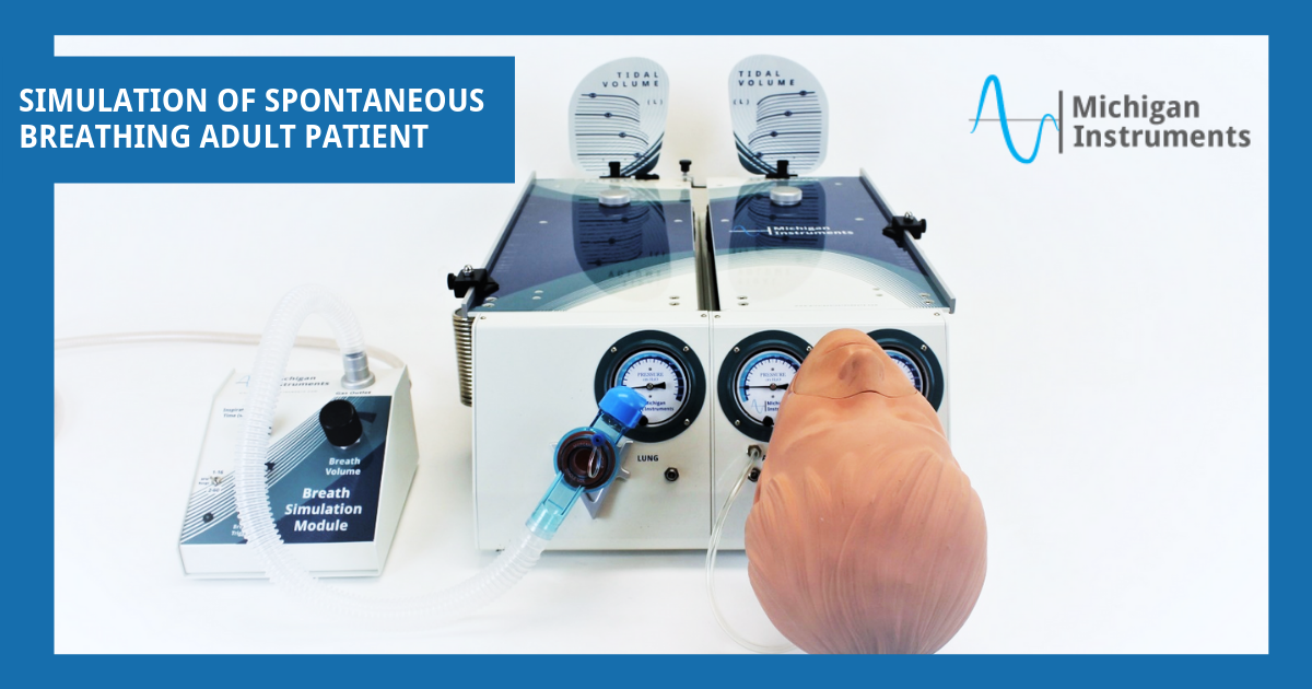
Simulation of Spontaneous Breathing Adult Patient
Application Purpose
This setup and application may be used to assess the performance of various techniques and apparatus that support the ventilation and oxygenation of spontaneous breathing adult patients.
REQUIRED MATERIALS
❶ Dual Adult Model of TTL® or Dual Adult PneuView® System with Standard Accessories
❷ BSM Breath Simulation Module (or another ventilator for “lifting lung”)
❸ Adult Head Simulation Module (HSM-A) (optional)

General Setup
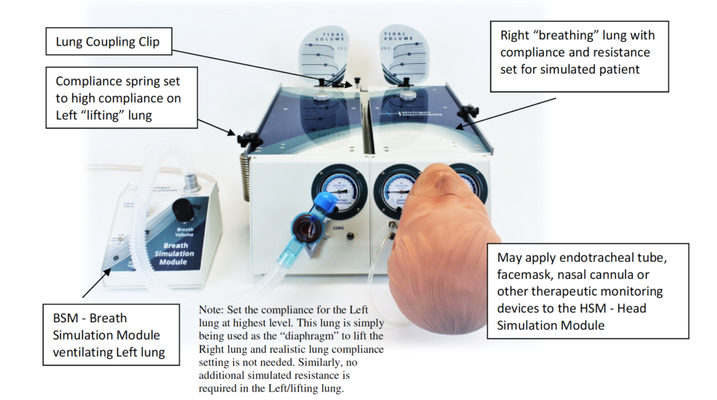
For the purposes of this guide, the left (L) lung of the TTL will be used as the “lifting lung” and the right (R) lung will be the “breathing lung”. (In actuality, the assignment could be reversed.)
The lifting lung essentially serves as the “diaphragm” in this simulation, which when lifted and coupled with the breathing lung, creates a negative pressure in the breathing lung that results in gas being drawn into the lung.
- Attach the “Lung Coupling Clip” to the lifting (L) lung as shown in the illustration below.
- Set the compliance of the lifting lung to .10. Do not add a resistor to the setup for this lung.
- Set the compliance on the breathing lung as desired for this simulated patient. (Michigan Instruments suggests a nominal/starting compliance of .05 L/cmH2O.)
- Add a PFA (Parabolic Flow Adapter) Resistor to the front of the unit for the (R) breathing lung. For adult patients, MII recommends initial use of an Rp5 or Rp20 PFA.
- Connect the MII Breath Simulation Module (BSM) to the (L) lifting lung. When the BSM is turned on and adjusted to the desired rate and tidal volume, the (L) lung will be rhythmically ventilated to generate a lift of the Top Plate of the (R) lung, resulting in a simulation of spontaneous breathing in that (R) lung.
Note: Michigan Instruments offers the Breath Simulation Module as a simple and relatively inexpensive way to fill the lifting lung with variable breath rates and volumes. However, almost any positive pressure ventilation device may be used to fill the lifting lung. A more sophisticated breathing pattern may require a more sophisticated ventilation device to fill the lifting lung.
- Connect the apparatus being used, tested, developed, evaluated or demonstrated to the airway connector or Head Simulation Module.
Note: For many applications, a Head Simulation Module (as shown below) may be added to the TTL / PneuView setup to enhance the simulation and facilitate training and evaluation of various techniques and apparatus.
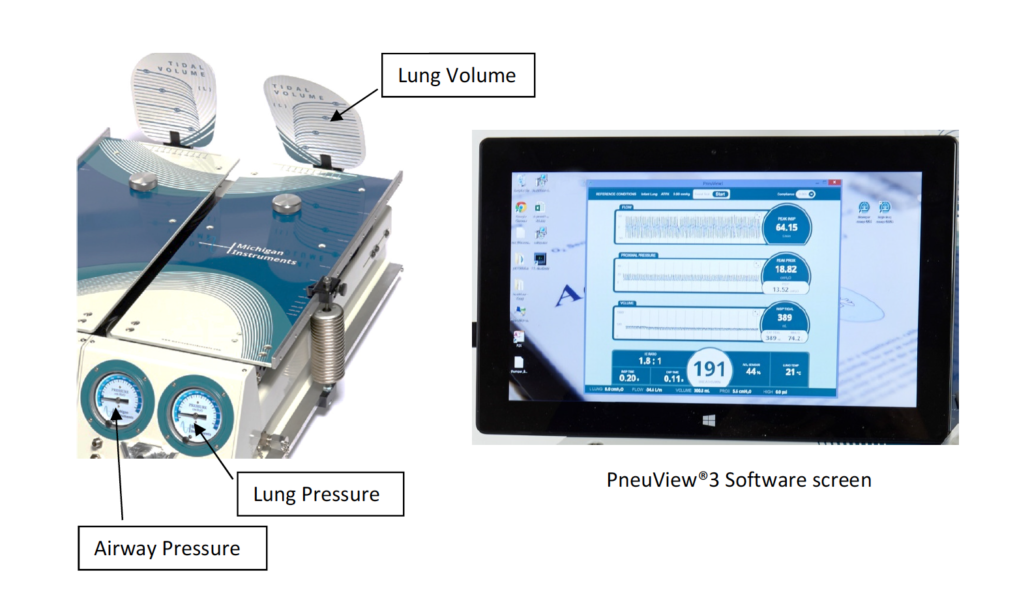
PneuView Notes:
If using the PneuView System, start the PneuView Software and make appropriate selections in the Conditions screen. Select “Right Lung” as this is the spontaneous breathing lung connected to the apparatus in question.
Volumes indicated on the TTL volume scale will be accurate, however, because pressure changes in the lung are used to measure and calculate flow and volume values in the PneuView software, some spontaneous breathing simulations will result in inaccurate flow and volume readings. If you have questions, please contact Michigan Instruments.
Regarding Simulation Applications
Michigan Instruments’ “Application Notes” documents are intended to provide some guidance and suggestions for use of the Test Lung Simulators. They do not encompass the range of applications for which the TTL and PneuView Systems are appropriate. We welcome your suggestions for future Application Notes and encourage you to share your own experiences and applications with us here.

